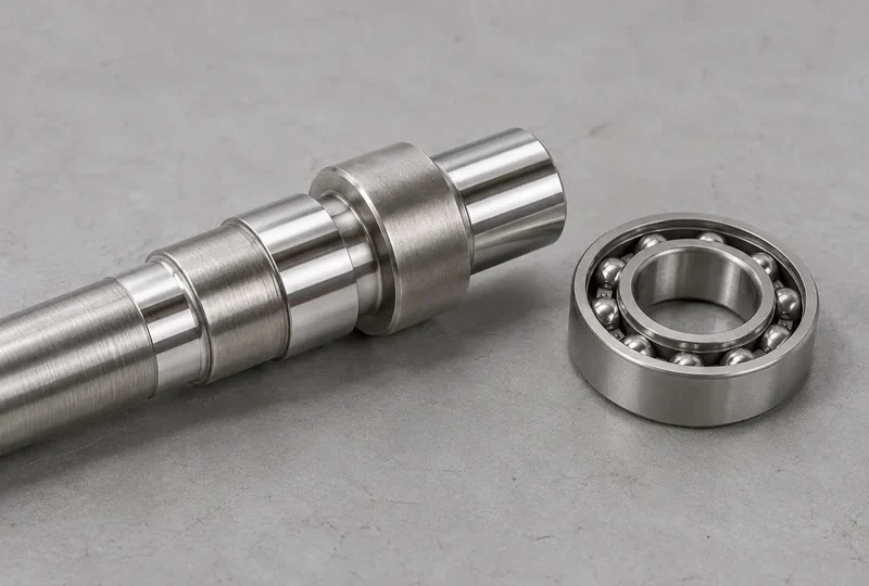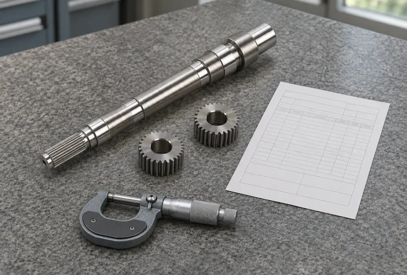


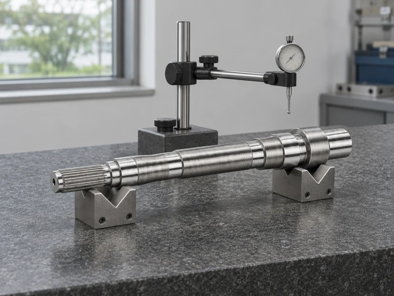
Circular runout evaluates the variation at an individual circular section as a shaft rotates about its specified datum axis. Total runout evaluates the entire controlled surface relative to that axis. Passing several circular checks does not automatically demonstrate compliance with a total-runout requirement.
For motor shafts and drivetrain components, the distinction matters at bearing seats, seal tracks and locating faces. Before comparing inspection results, confirm the drawing’s control, datum reference, controlled surface and measurement method. “Shaft runout: passed” is not a reproducible acceptance record.
Compare the controls before choosing the inspection
KEYENCE’s runout guide explains the sectional scope of circular runout and the whole-surface scope of total runout, both requiring a datum. Apply the governing drawing standard for the complete tolerance interpretation.
| Question | Circular runout | Total runout |
|---|---|---|
| What is assessed? | Each applicable circular element independently | The complete indicated surface collectively |
| What does a radial check observe? | Variation during rotation at one axial section | Variation over rotation and the controlled surface length |
| Can the indicator be reset between locations? | Separate section results may be assessed individually | Independent re-zeroing must not erase variation between sections |
| What belongs in the report? | Section positions, datum setup and readings | Surface coverage, datum setup and the overall evaluation |
Total runout is not simply a label for a stricter number. It changes the spatial scope of the control. Choosing it everywhere without a functional reason can add manufacturing and inspection work without resolving the actual assembly requirement.
The reference axis is part of the result
A shaft may have center holes, two bearing journals and an output spline. These features do not automatically define the same inspection axis. Follow the datum references on the drawing and establish an approved method for simulating them.
Supporting the shaft on convenient V-blocks or rotating it between centers can be useful for a shop check. Such a setup is not automatically equivalent to the drawing’s datum system. Record which surfaces provide support, how the part is constrained, the contact arrangement and the alignment check.
If buyer and supplier disagree, compare setups before blaming the instrument. A difference in support surfaces, probe position or axial restraint may mean the two teams are measuring different conditions.
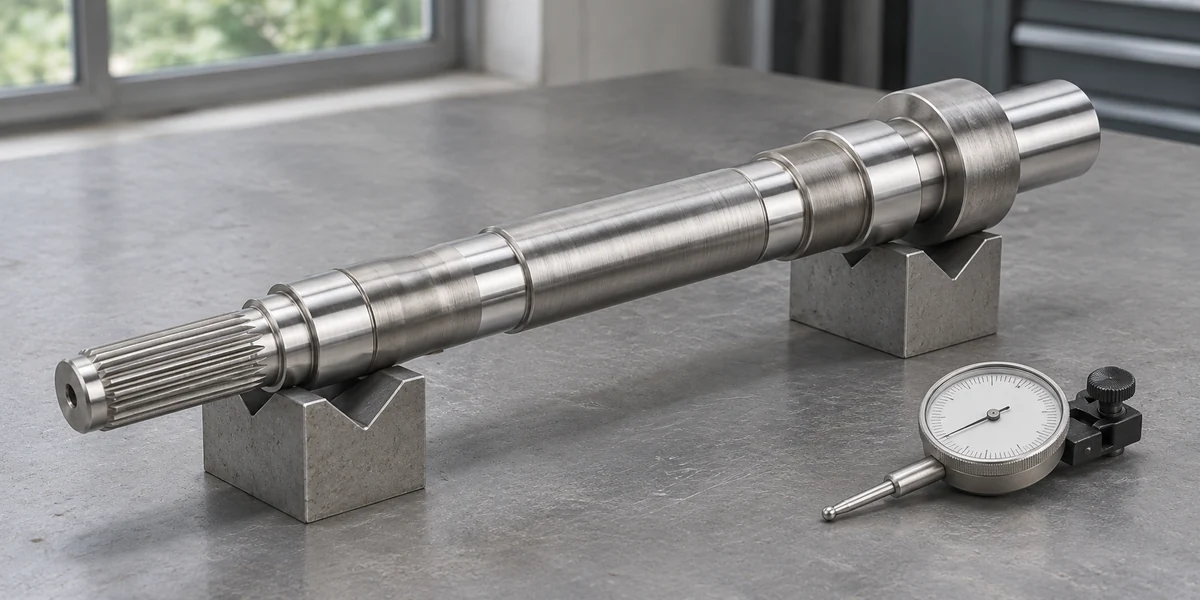
Why a set of small section readings can miss a surface problem
Consider an illustrative cylindrical seat with nearly round sections but a diameter that changes along its length. An indicator reset at each section could show little rotational variation locally. That does not establish that all points on the complete surface lie within the specified total-runout zone relative to the datum axis.
The lesson is about the inspection strategy, not an acceptance limit: preserve a common reference when evaluating the complete surface. Record the controlled length and the sampling or scanning strategy. A few selected locations may be a production sampling method, but the method must be adequate for the requirement it claims to verify.
Keep radial and face checks separate
For a cylindrical journal, the probe observes variation in the radial direction. For an end face or shoulder, the observation direction and controlled surface differ, as illustrated in Mitutoyo’s radial and axial runout guide. A low radial reading on a bearing seat does not establish that the adjacent locating face meets its face-runout requirement.
Identify the face or diameter on the drawing and record the probe path. On a face, the measurement radius matters to interpreting and reproducing an indicator check. On a journal, axial locations matter. Avoid one unlabeled “TIR” result for several different features.
Do not convert every TIR result into center offset
Total indicated reading is the difference between the highest and lowest indicator readings in the stated measurement. It can include part geometry, alignment and setup contributions. It is not generally a direct measurement of eccentricity.
For the idealized case of a perfectly circular cylinder rotating about a parallel, offset axis in a perfect setup, radial TIR equals twice the offset. Real shafts can depart from those assumptions. Halving a measured TIR without establishing the model can produce an unsupported center-offset claim.
Runout also does not replace a balance requirement. A geometric inspection and a mass-distribution assessment answer different questions. Keep their specifications and records separate.
A repeatable runout inspection record
- Identify the part, revision, surface, drawing control and datum references.
- Record the approved fixture and support method, including the features used to establish rotation.
- Inspect and prepare contact surfaces according to the measurement procedure; identify damage that could affect seating.
- State probe direction, contact location, controlled length and any axial restraint.
- Record the reading range and measurement coverage without removing required between-location variation.
- Repeat the setup as needed to evaluate whether remounting materially changes the result.
- Retain instrument identification, relevant conditions, results and disposition.
This is a proposed reporting checklist. The drawing, applicable standard and approved measurement procedure determine the acceptance method.
Connect the requirement to the shaft’s function
When requesting custom shaft manufacturing, send the mating-bearing or seal information, functional datum scheme and finished-part requirements. If the drawing only says “low runout,” identify that as an open design item before quotation.
TAITECH can review the supplied drawing and requested inspection scope with your enquiry. Include the existing measurement procedure when matching a repeat order or resolving a discrepancy. The guide to gear-shaft features provides a starting point for identifying the journals, shoulders and interfaces that the drawing must relate.