

When a gear inspection report arrives, check the part revision, measured flank and nominal tooth shape before judging the plot. A trace near the tip may bend away from an unmodified involute because the drawing specifies tip relief. Compare it with the intended profile and the evaluation limits marked on the chart.
Find the trace and its evaluation window
Profile measurements follow the tooth from the root side toward the tip. Helix measurements, often labeled lead on shop reports, run across the face width at a specified measurement diameter. The horizontal axis might use roll length for profile and axial position for helix. Read its label. A vertical offset or change of scale can make two plots look quite different on paper.
Record the start and end of the evaluated segment. A probe may travel through a region that the calculation excludes. Check that any exclusion matches the drawing or applicable measurement practice, especially near a tip break or end chamfer. Identify any applied filter before comparing a report with a second machine’s results. ISO/TR 10064-1 tooth flank measurement guidance.
Read slope, form and total deviation together
| Reported quantity | What to look for |
|---|---|
| Slope deviation | The overall tilt relative to the specified design within the evaluation range. Confirm the chart’s sign convention. |
| Form deviation | The residual shape after accounting for the fitted slope according to the evaluation method. |
| Total deviation | The overall spread relative to the design across the evaluated range. Check the reported value against its own limit. |
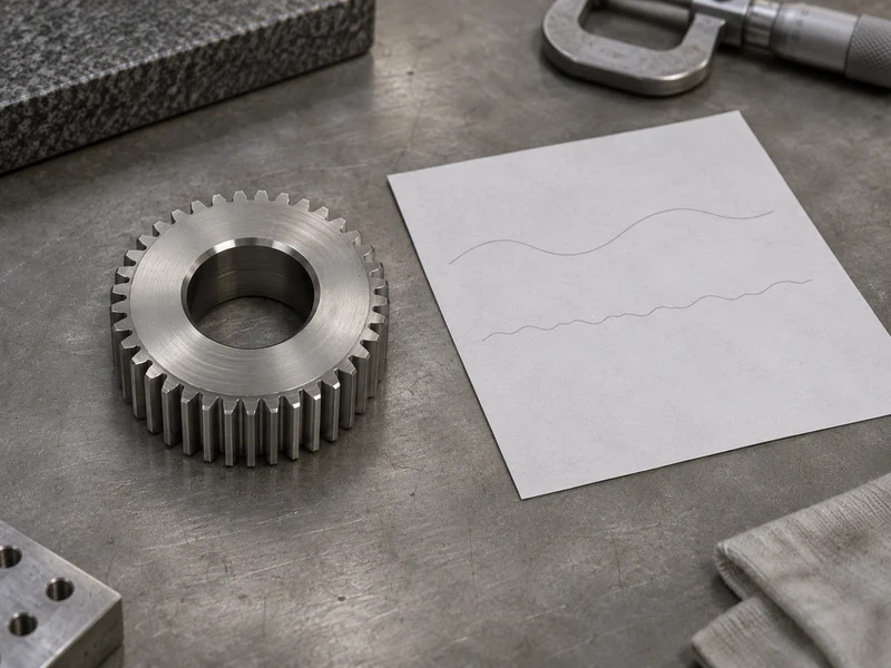
A largely straight but tilted trace can have a small form result and a larger slope result. A wavy trace may have little overall tilt and still have appreciable form deviation. Avoid adding the slope and form numbers to reconstruct total deviation. Each quantity follows its own evaluation procedure. ISO 1328-1 flank deviations.
Use the pattern to choose the next check
Suppose every sampled right flank shows a similar lead tilt. First check the specified design, helix hand, fixture datum and measurement direction. Repeat a selected trace after remounting the part and compare the same tooth and flank. If the pattern persists, compare it with the left flanks and with another piece from the same setup. A repeated pattern warrants a closer look at the generating or finishing setup. A change after remounting points the investigation toward the measurement setup first.
When asking a supplier to review a report, send the uncropped plots, part revision, nominal modifications, measured teeth and evaluation settings. Mark the affected region so both teams can repeat the same check. Send a gear drawing and inspection report for review.