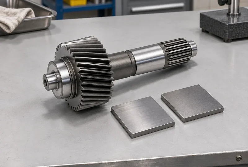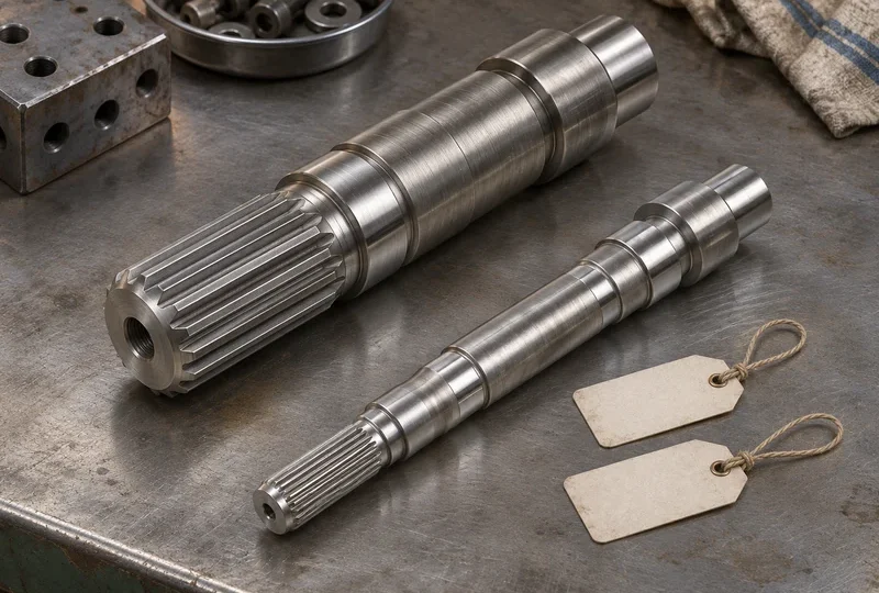


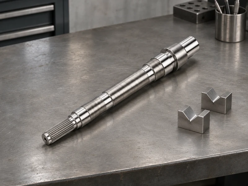
A bare shaft balance report describes the shaft in its test setup. The complete rotor adds parts such as the rotor stack, sleeves and retaining hardware. Each can change the mass distribution, so the drawing and purchase order should say which assembly state must meet the residual unbalance limit and who checks it.
Name the part as it will be balanced
List the part number, revision, mass and service speed for the balance requirement. State which pieces are installed, their indexed positions, and the convention for any key or temporary hardware. Identify the journals or adapters used to mount the part on the machine. If the rotor will be disassembled after balancing, specify whether parts are match-marked and what must be rechecked after assembly.
ISO 21940-11 addresses rotors with rigid behaviour. ISO 21940-12 addresses rotors with flexible behaviour. Have the design owner identify the applicable part, edition and amendments for the actual rotor and operating conditions. ISO 21940-11 scope and ISO 21940-12 scope.
Give the inspector a quantity and a plane
State the permissible residual unbalance in the agreed units, for example g·mm, and identify the applicable tolerance planes. Specify allowed correction locations and methods separately. If the machine reports results in correction planes that differ from the tolerance planes, agree on how the readings will be related to the acceptance limits. Record the measurement speed as well as the service speed used to establish the requirement.
| Acceptance item | Record on the report |
|---|---|
| Tested configuration | Part or assembly ID, revision, installed components, keys, fixtures and orientation marks |
| Limits and results | Standard reference, service and test speeds, plane locations, units and residual results by plane |
| Repeatability | Repeat check method, remounting conditions and disposition if the reading changes |
| Handoff | Allowed assembly work after the test and which changes trigger a recheck |
Assign the final acceptance step
If the shaft maker balances the bare part, give that step its own limit and report. Assign the assembly balance check to the team that controls the installed parts and their orientation. After a sleeve replacement or correction that changes mass distribution, use the agreed recheck procedure before the assembly returns to service.
If the system has a vibration limit, specify the operating points and measurement locations for the installed motor. Bearings, alignment and structural response can all affect those readings. Record the balance machine result and the installed vibration result against their respective limits.
For a shaft quote, send the drawing and mark which balance requirement belongs to the supplied shaft. Include the fixture assumptions and the report fields your receiving team needs. Discuss a custom motor shaft.