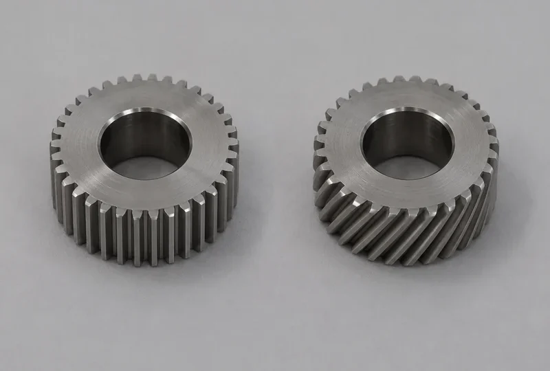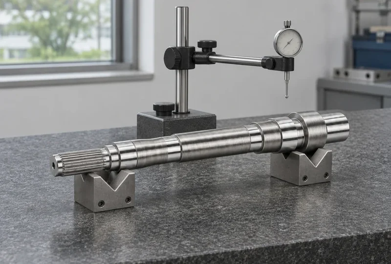


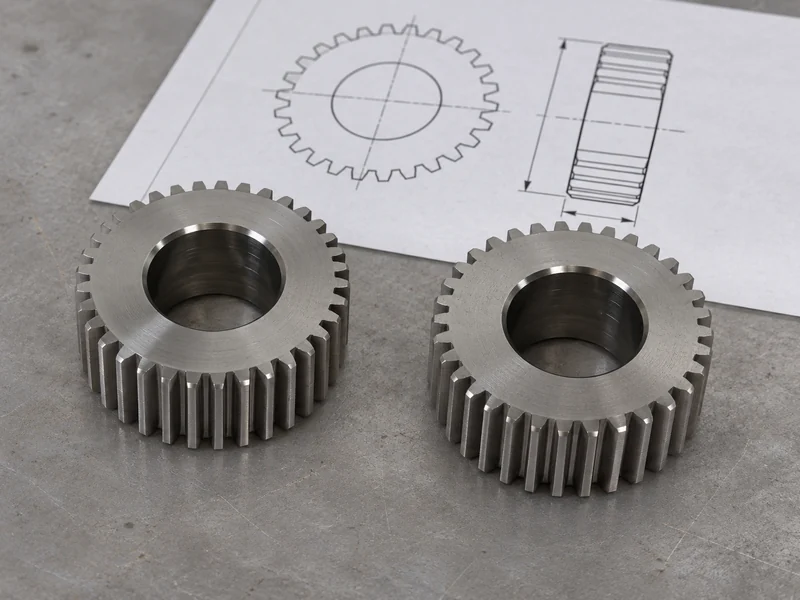
Gear backlash can be adjusted through tooth thickness, operating center distance or a coordinated design of both. For a fixed housing, tooth-thickness allocation is usually the more direct design variable; moving the shaft centers changes the operating mesh and must be reviewed as a system change. Neither method should begin with an unexplained instruction to “remove all play.”
This guide concerns conventional involute cylindrical gearing. Its purpose is to help a buyer and designer define a measurable pair-level requirement, not to provide a universal backlash value.
Specify what the backlash number means
Backlash is clearance between mating tooth flanks when the opposite flanks are in contact. The reported value depends on how that clearance is expressed. Transverse backlash is associated with the plane perpendicular to the gear axis; normal backlash uses the direction normal to the tooth surface as defined by the relevant method. Angular backlash expresses the free rotational movement at an identified member.
These values should not be compared without their definitions. A small angle at one shaft is not automatically the same linear clearance at a different radius, and a gearbox output reversal measurement can include several meshes and interfaces.
For a simple tangential displacement at a stated radius, j = rθ, with θ in radians. As arithmetic only, 0.05 mm at a 50 mm radius corresponds to 0.001 rad, approximately 0.057°. That conversion says nothing about whether 0.05 mm is suitable for a particular gear pair.
Separate the two design levers
SDP/SI’s backlash reference identifies tooth thickness and operating center distance as fundamental contributors. For an external involute pair, increasing center distance generally increases backlash, while reducing tooth thickness can provide clearance at a specified center distance.
| Design lever | Useful review context | Checks that remain necessary |
|---|---|---|
| Tooth-thickness allocation | Housing and shaft centers are fixed; individual gears need controlled acceptance | Strength, tooth form, production variation and specified measurement method |
| Center-distance adjustment | The assembly permits an approved position change or adjustment mechanism | Operating geometry, contact, bearing and housing interfaces, and adjustment retention |
| Coordinated change | A new design or formally approved redesign can change several parameters | Complete mesh calculation and assembly verification |
The tooth-count ratio remains a separate kinematic definition. That does not make a center-distance change consequence-free: the operating mesh geometry and engagement conditions still require review. For an internal gear pair or a different gear type, use the appropriate geometry rather than transferring the external-pair rule without checking it.
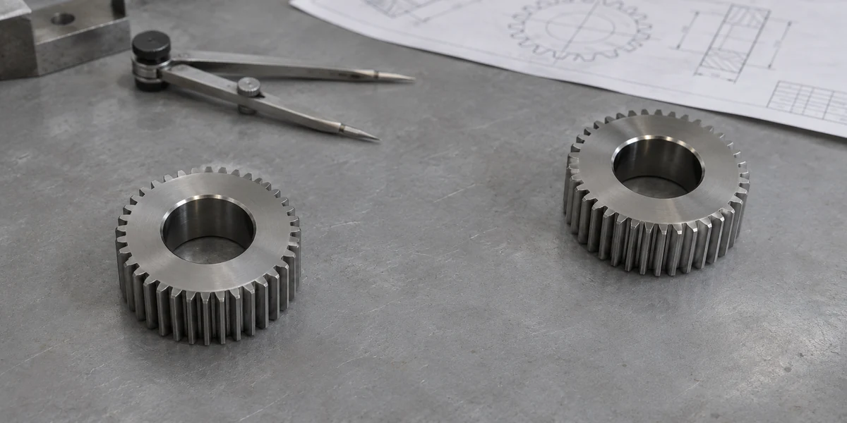
Do not use profile shift as a shorthand for thinning teeth
Profile shift affects more than clearance. If a supplier proposes changing it to achieve a backlash target, request the revised gear definition and the checks supporting that proposal. Do not approve a negative shift as a default shop adjustment while leaving the drawing’s other assumptions untouched.
Likewise, “cut slightly deeper” is not a complete production instruction. Agree the finished tooth-thickness requirement and how it will be measured, together with the governing tooth geometry. The process adjustment must deliver the approved design.
Build the requirement around the assembled pair
Backlash varies with the actual tooth thicknesses, mounting conditions and geometry of the mating components. A single loose-gear measurement therefore cannot close every assembly requirement. Define both the component controls and the pair-level acceptance method.
A useful allocation review contains four groups:
- Nominal design: gear pair, tooth definition, operating center distance and intended clearance expression.
- Manufacturing variation: tooth-thickness limits and other specified deviations that affect the mesh.
- Installation variation: shaft and bearing locations, runout and assembly references.
- Operating change: temperature, load-induced movement and relevant wear assumptions.
Have the design owner evaluate the stack using a consistent geometric model. Do not add unrelated micrometre values measured in different directions as though they were directly interchangeable.
Define the inspection conditions before negotiating the limit
| Acceptance field | What to state |
|---|---|
| Mating components | Part numbers, revisions and whether a master or production mate is used |
| Assembly geometry | Center distance, support arrangement and axial position |
| Reported quantity | Normal, transverse, tangential-at-radius or angular result, with units |
| Test conditions | Temperature, restrained member and applied checking load or torque |
| Coverage | Specified positions around the mesh and treatment of minimum and maximum results |
| Decision | Approved range, disposition process and responsible reviewer |
A reversal reading taken under substantial torque can include elastic deformation as well as clearance. If the target concerns lost motion under load, define it accordingly rather than relabeling it as unloaded tooth backlash. Keep the measurement tied to the buyer’s actual functional concern.
Make the RFQ explicit about what can change
Tell TAITECH whether the housing centers are fixed, whether both gears are in the supply scope and whether design changes are allowed. Include the mating drawings, finished tooth-thickness controls and agreed pair-level test with your custom gear review.
For gears and gear shafts made to drawing, an unresolved backlash target should appear as an open engineering item in the quotation. Resolve its definition and acceptance conditions before authorizing samples or changing a repeat-order component.