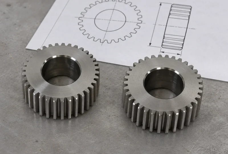


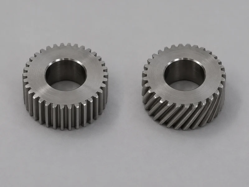
Choose between spur and helical gears by evaluating the complete transmission: duty cycle, noise target, bearing reactions, packaging, lubrication and manufacturing requirements. Helical teeth can provide axial overlap during engagement, but the resulting thrust must be supported. Spur teeth avoid that ideal mesh-generated axial thrust in a parallel-axis arrangement, yet they still need appropriate tooth design and axial retention.
This comparison concerns conventional external cylindrical spur and single-helical gears on parallel shafts. Crossed-helical, bevel and double-helical arrangements need their own analysis.
What changes at the tooth contact?
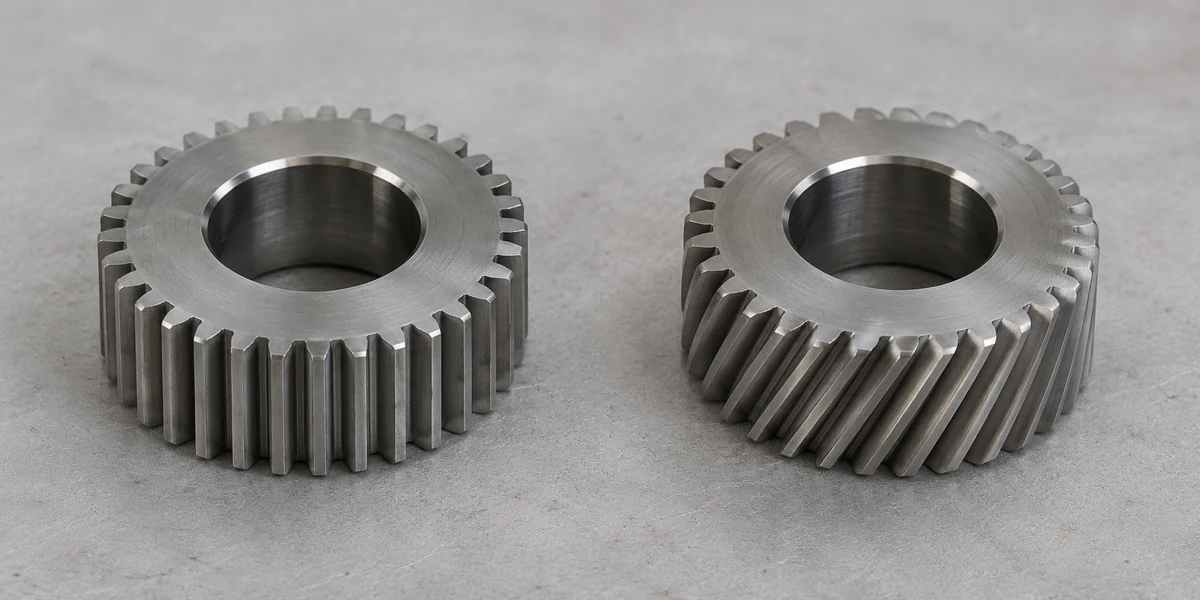
Spur teeth run parallel to the gear axis. Helical teeth follow an angled path around the gear. SDP/SI explains that helical overlap adds to transverse contact ratio. That engagement pattern can be useful when smoothness and noise matter, provided the geometry and operating conditions support the intended result.
It is not a guarantee that any helical gear will be quieter than any spur gear. Tooth modifications, manufacturing deviations, shaft and housing response, lubrication and operating load all affect the assembled result. Request noise evidence for the relevant duty and installation rather than treating tooth orientation as a noise rating.
Put the bearing arrangement into the comparison
A single-helical mesh introduces axial thrust in addition to tangential and radial force components. The gear-force model described by SDP/SI shows why the supports must be evaluated with the gear choice.
Review both torque directions where reversal occurs. Identify the locating bearing, shaft shoulders, retention and housing reaction. A proposed switch from spur to helical teeth can therefore require changes beyond the gear drawing. If the existing bearing system cannot accommodate the required reactions, a smoother engagement target does not make the conversion acceptable.
| Decision area | Spur candidate | Helical candidate |
|---|---|---|
| Engagement and noise | Evaluate the actual contact ratio, modifications and transmission response | Evaluate the benefit of overlap under the intended load and alignment |
| Support loads | Review tangential and radial mesh reactions | Include axial thrust and its reversal in the support review |
| Specification | Define tooth size, pressure angle, tooth count and modifications | Also identify helix angle, hand and normal or transverse system |
| Manufacturing | Review tool access, treatment and finishing requirements | Review the same route plus helix-related setup and inspection |
| Installed performance | Validate losses, temperature and noise in the assembly | Validate those outcomes including the thrust-bearing arrangement |
Compare efficiency under the same operating conditions
A single advertised efficiency number is rarely enough to choose a tooth form for an automotive duty cycle. Ask whether the figure refers to mesh efficiency or an assembled gearbox and whether it includes bearings, seals and lubricant losses.
For a useful comparison, hold torque, speed, lubricant condition and temperature basis consistent. Include the low-load operating region if it occupies much of the duty cycle. A candidate that performs well at one rated point may not have the same advantage across repeated acceleration, coast and reversal.
Use measured or calculated losses from the proposed assembly. Do not assign an unsupported fixed percentage advantage to either gear type.
A decision matrix that keeps unknowns visible
The following is an illustrative method for a passenger-vehicle auxiliary drive where noise and packaging matter. The weights are hypothetical project priorities, not industry benchmarks. Score only candidates that first satisfy mandatory torque, speed, life and interface requirements.
| Criterion | Example weight | Evidence needed before scoring |
|---|---|---|
| Noise in the installed duty | 30% | Agreed test or validated prediction at relevant operating points |
| Package and support integration | 25% | Assembly layout, bearing reactions and thermal movement review |
| Duty-cycle losses | 20% | Comparable loss map or calculations with stated assumptions |
| Manufacturing and inspection | 15% | Feasible route, inspection plan and supplier quotation |
| Assembly and service requirements | 10% | Mounting, retention, identification and replacement review |
For a 1–5 scoring scale, calculate the weighted total only after recording the basis for each score. Mark missing evidence as “open”; assigning a middle score to an unknown hides a development risk. Change the weights when the application changes. An intermittently operated starter reduction and a continuously running traction drive should not inherit the same priorities automatically.
Check the cost of changing an existing design
Before replacing a spur design with a helical alternative, compare the required center distance, face width, helix hand, support reactions and mating-part changes. Include the effect on tooling, treatment distortion allowance and final tooth inspection. A lower quoted loose-gear price can be outweighed by changes elsewhere in the assembly.
For a new project, ask suppliers to identify the assumptions behind each route. For a repeat component, retain the approved geometry unless the design owner authorizes a change.
Prepare comparable gear quotations
TAITECH’s gear and gear-shaft supply scope provides a starting point for custom component enquiries. Send the mating drawings, torque and speed duty, available bearing arrangement, noise target and quantities for a manufacturing review. Identify which tooth-form decision is approved and which remains under evaluation, so the response can separate component manufacture from unresolved system design.