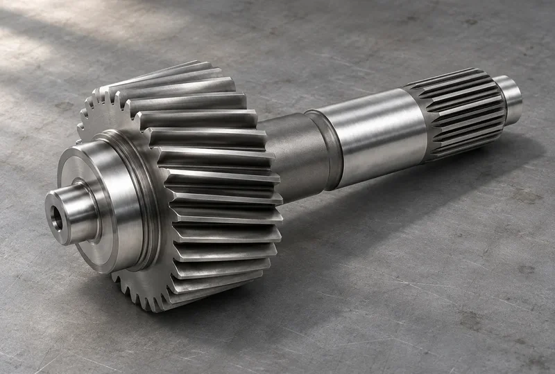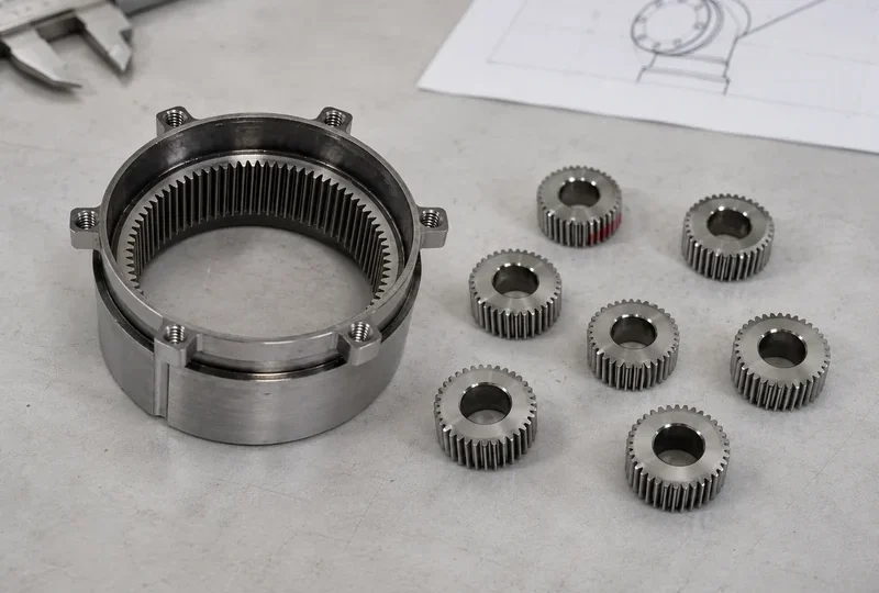


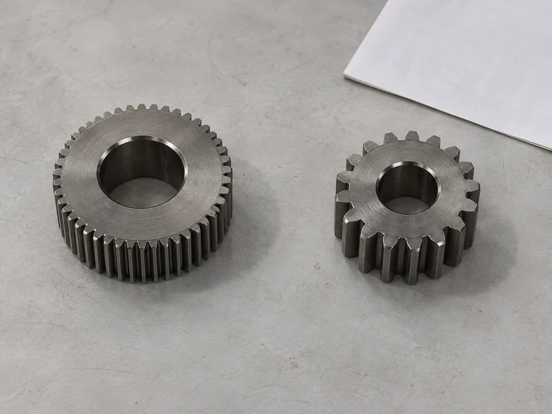
A drawing calls for a 24-tooth, 12 DP pinion. A second drawing lists 24 teeth and module 2. The tooth counts agree, but the first pinion has a 50.8 mm reference diameter and the second has a 48 mm reference diameter. If the drawings describe the same part, someone needs to resolve that 2.8 mm difference before a supplier selects a cutter or quotes the job.
Three ways to describe tooth size
Gear module is the reference diameter in millimeters divided by the number of teeth. Diametral pitch, usually written DP, is the number of teeth divided by the reference diameter in inches. Circular pitch is the distance along the reference circle from a point on one tooth to the corresponding point on the next. For a spur gear, the three conventions describe the same tooth spacing in different ways. See SDP/SI’s gear terminology and pitch formulas.
| Drawing field | Calculation | With 24 teeth and 12 DP |
|---|---|---|
| Reference diameter d | Tooth count ÷ DP, in inches | 2 in, or 50.8 mm |
| Module m | 25.4 ÷ DP, in millimeters | 2.11666… mm |
| Circular pitch p | π × m, in millimeters | About 6.65 mm |
Keep 12 DP as the controlling callout if that is what the released drawing specifies. You can show its metric equivalent on a review sheet, with enough digits for the calculation and a note identifying the controlling unit. Replacing it with module 2 changes the tooth system. Replacing it with 2.12 also changes the nominal value, even if the discrepancy is easier to miss.
Check which circle the diameter belongs to
Calipers across the tips of an external gear give you an outside dimension. The reference circle is a geometric construction inside those tips. For a standard unshifted external spur gear with an addendum equal to one module, the theoretical outside diameter is m(z + 2), where z is the tooth count. A 24-tooth module 2 gear of that form would have a 52 mm outside diameter and a 48 mm reference diameter.
That shortcut can help screen a sample if you know its tooth form. Tip modifications, profile shift and a different addendum convention can change the result. A measurement over pins or a span measurement, taken under a defined procedure and interpreted with the tooth geometry, gives the reviewer more to work with than an outside diameter alone. Keep both the original drawing and the measured value in the file.
The plane matters on a helical gear
In the transverse plane, perpendicular to the gear axis, d = z mt. If the drawing gives normal module mn and reference helix angle β, then mt = mn / cos β. For example, a 30-tooth helical gear with a normal module of 2 mm and a 30° reference helix angle has a reference diameter of about 69.28 mm. Multiplying 30 by 2 gives 60 mm because it omits the conversion to the transverse plane. Label the plane beside the pitch value and the pressure angle on the review sheet. See SDP/SI’s technical section on helical gear geometry.
Reconcile both drawings before release
- Copy the released pitch callout, tooth count and drawing revision for each gear into a two-column worksheet.
- Put both pitch values in the same units and plane. Keep the source values alongside the conversions so the reviewer can trace any discrepancy.
- Check the pressure angle, helix angle and hand where applicable. Add the specified center distance, profile shift or tooth thickness data, and the acceptance measurement. Matching pitch resolves one part of the mesh definition.
- If the converted values disagree, ask the drawing owner to confirm the controlling callout or release a corrected revision before tooling.
For a custom gear or gear shaft inquiry, send both mating drawings and identify the field that disagrees. Include the mounting center distance and any measured values with their method. Use the custom component review form.