

Gear pressure angle sets the direction of the force at an involute tooth mesh. In an external spur pair, raising the working pressure angle increases the radial force for a given tangential force. A proposed change from 20° to 25° therefore needs a look at the bearing reactions as well as the tooth geometry.
Which pressure angle is on the drawing?
The reference pressure angle defines the nominal tooth system. The working pressure angle describes the installed mesh, where the line of action is inclined to the common tangent at the working pitch point. For an external involute pair, the base circles stay the same when you change the mounting center distance. Moving the shafts farther apart increases the working pressure angle. Write down both values if the installed center distance differs from the reference condition. See SDP/SI’s explanation of involute mesh geometry.
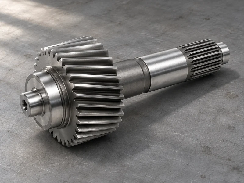
A helical gear drawing may give a normal pressure angle measured in the plane normal to the tooth direction. The angle in the transverse plane is a different value. Use the appropriate transverse working angle for the radial force calculation and account for axial thrust separately. Keep the plane visible in the calculation so the value can be checked against the drawing.
A 205 N change at the mesh
Take two hypothetical external spur designs at the same 80 mm working pitch diameter and 80 N·m of transmitted torque. The tangential force at the mesh is twice the torque divided by the working pitch diameter, or 2,000 N in both cases. For this simplified static example, the radial force is the tangential force times the tangent of the working pressure angle.
| Working pressure angle | Tangential force | Radial separating force |
|---|---|---|
| 20° | 2,000 N | 728 N |
| 25° | 2,000 N | 933 N |
To find the bearing reactions, apply the mesh force where the teeth actually engage. An overhung pinion and a pinion centered between two bearings distribute the same force differently. The example isolates the effect of pressure angle and leaves out dynamic loads and housing deflection. See SDP/SI’s gear force diagrams.
Review the root and the contact path together
A higher reference pressure angle can give a tooth a fuller root section and may help with undercut on a small pinion. How much it helps depends on the tooth count, profile shift and the generated fillet. Use the actual root geometry in the bending review. The cutter and its tip radius can affect that geometry even when the drawing still shows the same nominal module.
Recalculate the contact ratio for the proposed pair at its mounting center distance. Changing the tooth system changes the available path of contact. Check for tip or root interference as well, particularly where a small pinion or an internal gear limits the usable geometry. The contact ratio calculation and the interference check answer separate questions about the same mesh. See SDP/SI’s contact ratio reference.
When a replacement pinion has the right module
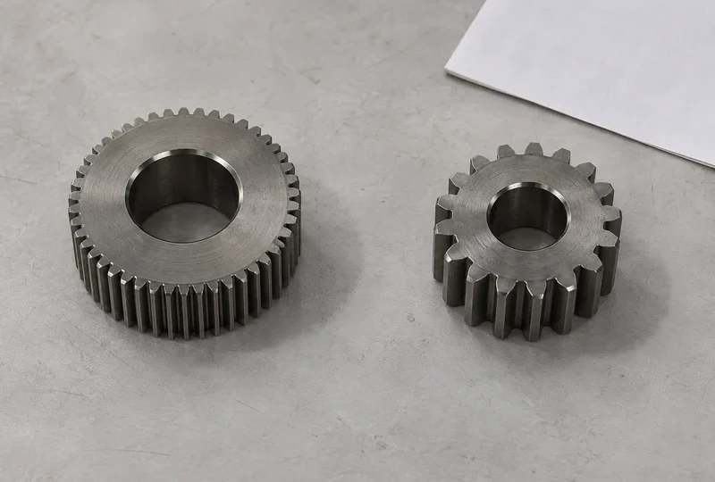
Before accepting it, compare the released tooth data for the pinion and the gear it will run against. For example, standard spur gears at the same module but with 20° and 25° reference angles have different base pitches. A matching bore, outside diameter or tooth count cannot establish the required involute mesh. If the mating gear’s pressure angle is unknown, put that field on the drawing query rather than taking it from a visually similar part.
Send the two drawing revisions, center distance and torque cases when asking about custom gears and gear shafts. Specify whether each angle is normal or transverse, and identify which values your assembly treats as fixed.