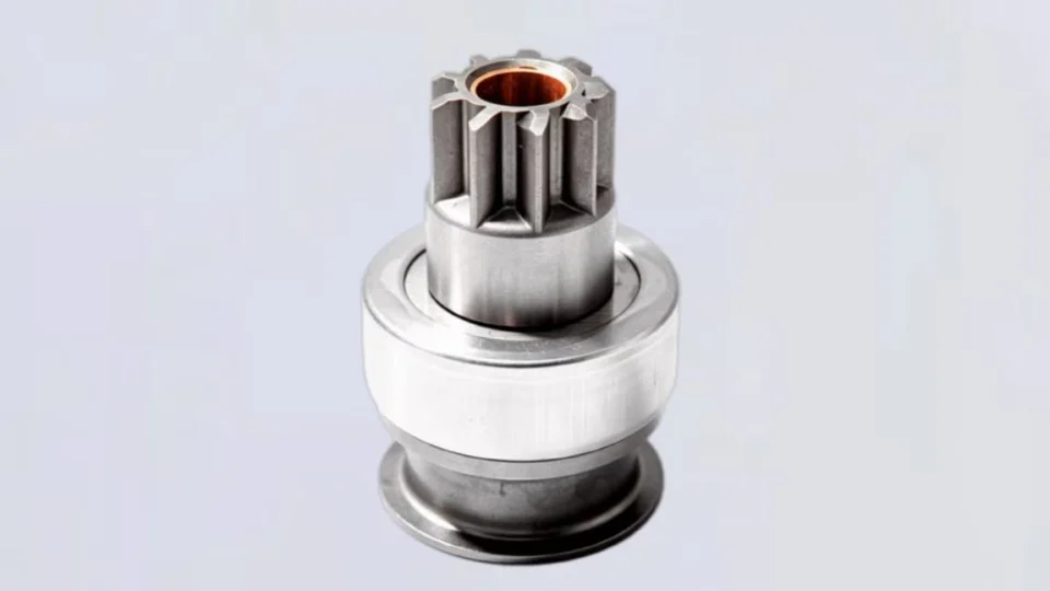


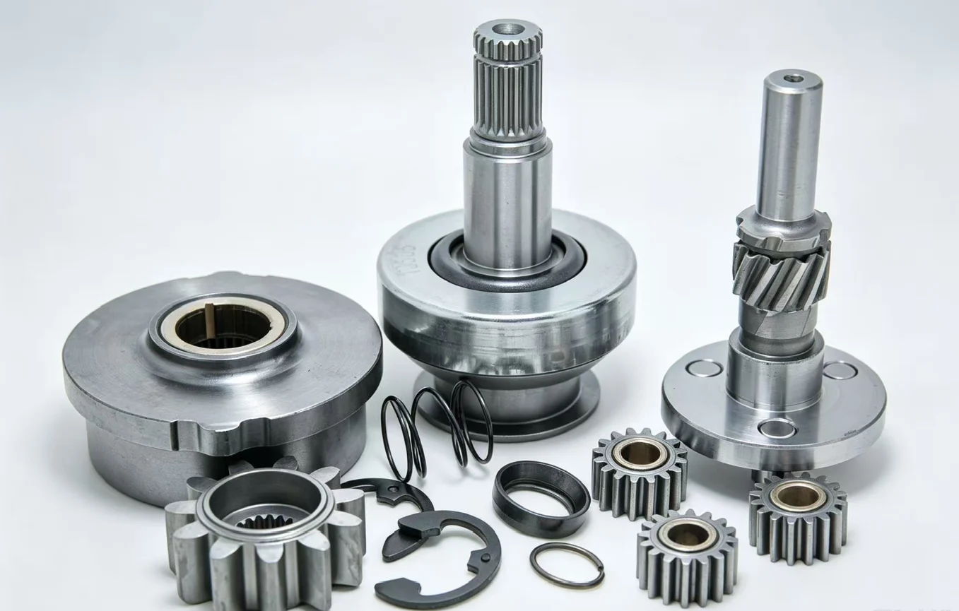
Why Do Gears and Shafts Fail to Work Together Properly?
Have you experienced excessive noise, vibration, shaft misalignment, or premature gear wear in a mechanical transmission? These problems often begin when gears and shafts are designed or manufactured separately without considering their interaction. A gear may meet its dimensional requirements, yet the complete assembly can still fail under real operating loads. Incorrect shaft stiffness, poor gear alignment, insufficient lubrication, and unsuitable material selection can all reduce transmission efficiency and service life. The consequences include unexpected downtime, higher maintenance costs, and expensive component replacement. For equipment manufacturers, choosing the right gear and shaft combination is essential. The solution is to evaluate the entire transmission system, including torque, rotational speed, tolerances, materials, and operating conditions, before production begins.\
How Do Gears and Shafts Work Together?
Gears transmit torque and control rotational speed, while shafts support rotating components and transfer mechanical power. Our company helps customers evaluate gear and shaft specifications, material options, machining requirements, and assembly tolerances to develop reliable transmission components for industrial applications. As a gear and shaft Manufacturer and Supplier, we support Customizable solutions, OEM production, and ODM development according to project requirements.
Understanding the relationship between gears and shafts is the first step toward building a reliable transmission. The following sections explain how power flows through an assembly, which engineering parameters matter most, and how manufacturers can reduce common failures through better design and production control.
1. How Do Gears and Shafts Transfer Mechanical Power?
The Role of Gears in Torque and Speed Conversion
A gear transfers motion through the engagement of its teeth with another gear. The gear ratio determines the relationship between input speed and output speed. In a simple external gear pair, a larger driven gear generally rotates more slowly than a smaller driving gear while delivering greater output torque, subject to transmission losses.
For a basic gear pair, the speed relationship can be expressed as:
Gear ratio = Number of teeth on the driven gear Number of teeth on the driving gear
If a 20-tooth pinion drives a 60-tooth gear, the reduction ratio is 3:1. With an input speed of 1,500 rpm, the ideal output speed is 500 rpm. The output torque increases approximately threefold in an ideal lossless system. In practice, bearing friction, tooth friction, lubrication, and other losses reduce the actual torque available.
The Role of Shafts in Power Transmission
A shaft supports gears, bearings, pulleys, and other rotating elements. It transfers torque while resisting bending forces and maintaining the required component positions. A shaft that is too small may twist excessively or fail under combined loading. A shaft that is too flexible can also change the gear contact pattern, increasing noise and uneven tooth wear.\
For a solid circular shaft under ideal elastic torsion, the maximum shear stress can be estimated using:
\τ = 16T / (πd³)\\
Here, τ represents maximum torsional shear stress, T is applied torque, and d is the shaft diameter. Use consistent units when performing the calculation. This equation is a preliminary design tool. Actual shaft design must also consider bending, stress concentrations, fatigue, keyways, splines, and service conditions.
2. Why Are Gear and Shaft Alignment So Important?
Understanding Misalignment and Uneven Load Distribution
Gears need the correct relative position to maintain stable tooth contact. Shaft deflection, bearing clearance, housing distortion, and machining errors can shift the contact pattern away from its intended position. When the load concentrates near one end of a tooth, local contact stress increases. This can accelerate pitting, scuffing, tooth wear, and tooth-root fatigue.
Misalignment can also increase operating noise and vibration. In high-speed machinery, these effects may become more severe because dynamic forces interact with shaft and housing flexibility. Simply increasing gear hardness will not correct a fundamental alignment problem.
Key Parameters for Accurate Assembly
When reviewing a gear and shaft assembly, engineers should check the following parameters:
- \Shaft runout:\ Controls the variation in the position of a rotating surface relative to its reference axis.
- \Bearing seat dimensions:\ Affect bearing fit, shaft support, and rotational accuracy.
- \Gear bore tolerance:\ Determines how the gear fits onto the shaft.
- \Center distance:\ Influences backlash and tooth engagement in a gear pair.
- \Axial positioning:\ Helps maintain the intended gear face alignment and clearance.
- \Shaft deflection:\ Must remain within acceptable limits under operating loads.
These parameters should be evaluated together rather than treated as independent inspection items. For example, a gear bore may meet its drawing tolerance, but an unsuitable fit can still cause relative movement, fretting, or assembly difficulties.
3. Which Materials Are Suitable for Gears and Shafts?
Material Selection Based on Load and Operating Conditions
Material selection affects strength, wear resistance, machinability, cost, and service life. The correct choice depends on torque, rotational speed, shock loading, operating temperature, lubrication, and the required production volume.
Alloy steels are widely used for heavily loaded gears and shafts because their properties can be adjusted through heat treatment. Carburizing and hardening can provide a wear-resistant surface with a tougher core when the material and process are properly selected. Induction hardening may suit certain shaft journals and gear teeth. Through-hardening is another option for applications requiring suitable strength throughout the component.
Carbon steel may be appropriate for less demanding shafts and transmission components. Stainless steel can be considered where corrosion resistance is important, although the specific grade must still meet the required mechanical and wear performance. Cast iron is used in some gear applications, particularly where its damping characteristics and manufacturing economics are beneficial.
Heat Treatment and Surface Quality
Heat treatment does more than increase hardness. It influences fatigue strength, dimensional stability, residual stress, and resistance to tooth-surface damage. Excessive distortion after heat treatment can create machining and assembly problems, making process planning essential.
Gear load capacity calculations should consider both \tooth-root bending strength and surface contact durability. The ISO 6336 series provides calculation methods for the load capacity of cylindrical involute spur and helical gears, including factors associated with materials and strength. Its applicability depends on the gear type and calculation assumptions. https://www.iso.org/standard/63819.html” target=”_blank” rel=”noopener noreferrer”>ISO 6336-1:2019\ describes the basic principles and general influence factors for these calculations.
For shaft components, engineers must separately assess torsional stress, bending stress, fatigue, and stress concentrations. A material suitable for a gear is not automatically the best choice for its mating shaft.
4. How Should You Choose Gear and Shaft Specifications?
Compare the Main Design Parameters
Before requesting a quotation from a gear Manufacturer or shaft Supplier, prepare the operating requirements. This information helps the engineering team evaluate manufacturability and avoid unnecessary redesign.
| Parameter | Gear Considerations | Shaft Considerations |
|---|---|---|
| Torque | Tooth bending and contact stress | Torsional and combined stress |
| Rotational speed | Dynamic loading, lubrication, and noise | Critical speed, balance, and vibration |
| Dimensional accuracy | Tooth profile, pitch, runout, and backlash | Diameter, straightness, runout, and concentricity |
| Material | Wear resistance and tooth strength | Strength, stiffness, and fatigue resistance |
| Heat treatment | Surface durability and tooth-root strength | Journal durability, fatigue performance, and distortion control |
Illustrative Gear Ratio Comparison
The following example shows how changing the gear ratio affects output speed and ideal torque. It assumes an input speed of 1,500 rpm and an input torque of 10 N·m, with no transmission losses. These are illustrative values, not universal design recommendations.
| Gear Ratio | Ideal Output Speed | Ideal Output Torque | Typical Design Effect |
|---|---|---|---|
| \2:1\\ | 750 rpm\ | 20 N·m\ | Moderate speed reduction |
| \3:1\\ | 500 rpm\ | 30 N·m\ | Greater torque multiplication |
| \5:1\\ | 300 rpm\ | 50 N·m\ | Higher reduction and torque multiplication |
These calculations illustrate the basic relationship between speed and torque. They do not confirm that a particular gear or shaft can safely withstand the resulting load. Tooth geometry, shaft diameter, bearing arrangement, materials, duty cycle, and service factors must all be evaluated before finalizing a design.
5. What Manufacturing Processes Improve Gear and Shaft Reliability?
Precision Machining and Gear Cutting
Manufacturing quality directly affects how gears and shafts perform after assembly. Depending on the design, gear teeth may be produced by hobbing, shaping, or other suitable cutting methods. Grinding or additional finishing may be required to achieve tighter accuracy, improve surface finish, or meet demanding noise and performance requirements.
Shaft manufacturing commonly includes turning, milling, drilling, grinding, and spline or keyway machining. The process sequence should account for material condition, heat treatment, datum selection, and final inspection. Critical bearing journals and gear mounting surfaces deserve particular attention because their geometry affects alignment and support.
Inspection and Quality Control
Inspection should be based on the engineering drawing and the actual application requirements. Typical checks include:
- Dimensional inspection:Verifies critical diameters, lengths, fits, and geometric tolerances.
- Gear inspection:Evaluates tooth profile, lead, pitch accuracy, runout, and other specified characteristics.
- Hardness testing:Confirms that the specified heat-treatment requirements are met.
- Surface inspection:Identifies unacceptable damage, cracks, or finishing defects where applicable.
- Assembly testing:Checks backlash, rotation, contact pattern, noise, or operating performance as required.
Not every project requires the same inspection plan. A low-load commercial mechanism and a high-duty industrial gearbox have different risk profiles. The inspection scope should reflect the component’s function, the drawing, applicable standards, and customer acceptance criteria.
6. Why Work With a Gear and Shaft Manufacturer Offering OEM and ODM Services?
Customizable Components for Specific Applications
Standard components are suitable when their dimensions and performance match the application. However, many industrial projects require Customizable gear and shaft solutions because of restricted installation space, unusual torque requirements, specific mounting interfaces, or existing equipment constraints.
An experienced Manufacturer and Supplier can help review drawings, identify critical dimensions, evaluate material options, and select practical machining processes. This engineering discussion should take place before mass production, when design adjustments are easier and less expensive.
OEM Production and ODM Development
OEM projects generally focus on manufacturing components to the customer’s approved specifications.ODM\ projects may involve a broader development role, including design input, component optimization, and prototype evaluation, depending on the agreed scope of work.
For either model, buyers should establish clear technical documentation before production. Important items include:
- Approved drawings and revision control.
- Material grades and heat-treatment requirements.
- Critical tolerances and inspection methods.
- Production quantities and expected annual demand.
- Packaging, traceability, and delivery requirements.
Our company can discuss project-specific requirements for gear and shaft components and evaluate suitable manufacturing options according to the information provided. Buyers should confirm available processes, inspection capabilities, lead times, and quality documentation during quotation and technical review.
7. How Can You Prevent Premature Gear and Shaft Failure
Preventive measures begin with correct design and continue throughout production and operation. Even a well-manufactured assembly can fail if lubrication is inadequate, loads exceed the design envelope, or maintenance is neglected.
Use the following checklist during design review and troubleshooting:
- Confirm the load profile.\Record continuous torque, peak torque, speed, starts, stops, and shock loads.
- Verify shaft stiffness.Evaluate bending and torsional deflection under realistic operating conditions.
- Check gear contact.Confirm alignment, backlash, and load distribution using appropriate inspection methods.
- Select suitable lubrication.Consider speed, load, temperature, lubricant viscosity, and the manufacturer’s recommendations.
- Control manufacturing variation.Inspect critical dimensions and heat-treated components according to the drawing.
- Monitor operating conditions. Investigate abnormal vibration, rising temperature, metallic debris, and changes in noise.
Common failure symptoms can help narrow the investigation. Pitting may indicate surface fatigue or unfavorable contact conditions. Tooth-root cracks may be associated with excessive bending stress, fatigue, or stress concentrations. Fretting near a shaft-mounted gear can indicate relative movement at the interface. These symptoms require inspection and engineering analysis before assigning a definitive root cause.
Conclusion
Gears and shafts must be designed, manufactured, and assembled as a coordinated transmission system. Correct material selection, accurate machining, controlled alignment, and suitable load calculations improve reliability. Contact our team with your drawings and operating requirements to discuss Customizable gear and shaft components, OEM production, and ODM development.for your next project.