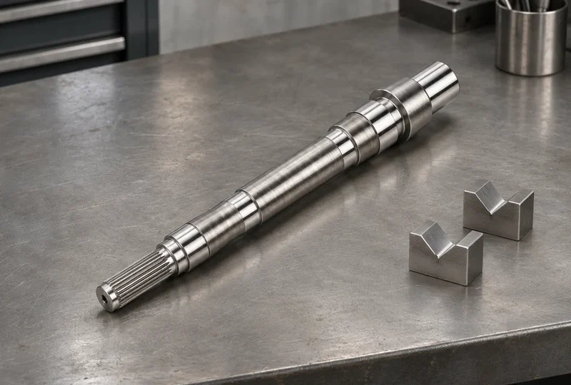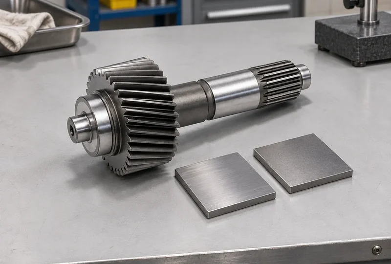


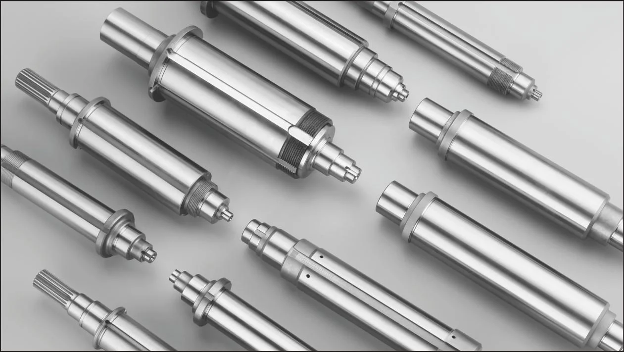
Send a shaft drawing for quotation with the bearing journals, rotor locating diameter, thrust face and torque interface marked. Ask the supplier to show how each of those features will be held and checked through machining. A motor shaft can meet every diameter on the drawing and still put the rotor seat off the axis established by the bearings. The manufacturing route has to preserve that relationship through changes in setup and material condition.
Start with the surfaces that locate the shaft in service
Identify the surfaces that support the shaft in the motor. On a typical stepped design, the bearing journals establish a functional axis and a shoulder sets an axial position. The rotor seat, seal track and spline may have requirements relative to those references. Put the functional datums and geometric controls on the drawing or the approved specification. If a drawing uses a datum at one end and the assembly locates on two journals together, raise the discrepancy before the route is priced.
It helps to review one longitudinal section with both the manufacturing and quality teams. Mark the support and seating surfaces, then identify which must be inspected after hardening, coating or polishing. A groove radius, seal surface or transition next to a spline can drive the process even when its dimension occupies only one line on the drawing. It can affect tool approach, grinding wheel clearance or where the part can be supported.
Quote the blank and the finished part together
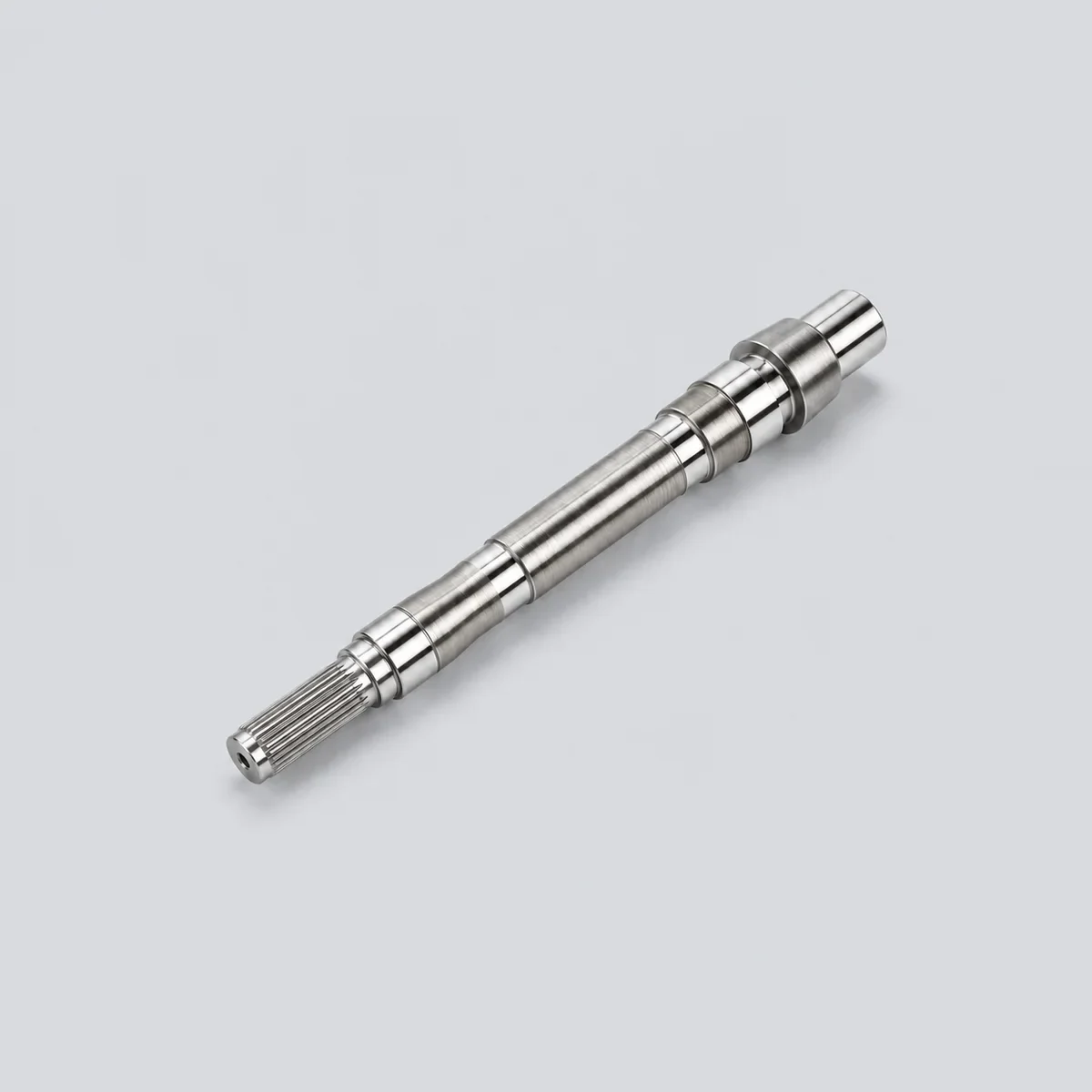
Round bar is often a sensible starting point for samples and small releases. It leaves room to change shoulder positions while the design is still moving, and the supplier can usually quote it without a dedicated forming tool. Check the maximum diameter and the amount of material removed over the rest of the length. A shaft with one large flange and long, small journals may spend much of its cycle turning away stock. At repeat quantities, a forged or otherwise near-net blank may merit a separate quotation. Include tooling, blank inspection and the machining allowance on the surfaces that will be finished.
A hollow shaft adds a decision about how the bore will be produced and verified. A hole that simply reduces mass needs different controls from a bore that locates another part or carries coolant. For an assembled shaft, ask how the joint is located during assembly and which geometry is rechecked afterwards. EMAG describes one production route for an assembled hollow rotor shaft that combines soft machining, joining, hardening and hard machining. Use such an example to discuss options for your drawing.
Follow the reference through each setup
During rough turning, establish references that can be picked up again. Check the largest shoulder, the minimum material remaining on finish surfaces and any temporary center features the manufacturer plans to use. A supplier may turn or grind between centers if the shaft geometry allows it. A different setup may locate on one journal and a face. Ask how the second setup relates its work back to the references used for final acceptance.
Work out when the torque features are made. Cutting a spline or keyway while the material is soft can make tool access and machining easier, while a required final geometry or surface condition may call for work later. The shoulder next to the spline deserves a side view with tool approach and relief shown. If the process needs more space than the drawing allows, resolve the feature before producing the blank. A change to relief or the usable tooth length can change how the mating hub seats.
| Before moving the part | Evidence to review | Decision if the evidence is missing |
|---|---|---|
| Release the blank | Grade, product form, incoming condition and stock on the major diameters | Confirm the material and envelope before machining |
| Send the part for heat treatment | Rough dimensions, locating features, treatment zones and stock at final surfaces | Resolve any thin stock or protected area before the treatment |
| Finish the journals and rotor seat | Post-treatment movement, usable setup references and remaining stock | Check that the approved route can clean up the surfaces on the required axis |
| Release the sample | Finished dimensions, surface finish and geometric results against the functional datums | Document the open characteristic and agree how to close it |
Leave enough material for the condition after treatment
Suppose a shaft has a locally hardened spline and two ground bearing journals. After treatment, the shaft has moved enough that one journal sits differently relative to the intended finish axis. The issue is whether the remaining stock lets the grinding setup clean up both journals on that axis. A report of the rough diameters alone leaves out where those diameters sit. Check movement and stock together before committing to the final setup.
Where a hardened surface will also be finished, take the material removed by finishing into account when agreeing the required condition. If a drawing calls for a specified depth or hardness after finishing, the inspection plan should say where and how it will be checked. For external heat treatment or other outside operations, record who supplies the instructions, who approves changes and who verifies the returned parts. Keep the lot identity with any material or treatment certificate required by the order.
Match the inspection setup to the drawing
Diameter, surface finish and runout answer different questions. Measure the fit diameter over its specified length. Check the surface texture with the agreed direction and method. Use the drawing datum for runout or another geometric control. If the shaft is located differently on the inspection fixture than it will be in the motor, agree how the fixture represents the functional setup. Circular and total runout on shafts.
For initial samples, request the measurements the receiving team needs before approving production. A sheet that says “journals OK” leaves the buyer without the actual readings, the drawing revision or the reference used to locate the part. Agree what should be reported as a measured value and what can be recorded as a gage result. First article inspection for drivetrain components.
When the prototype route changes for repeat orders
A sample machined from bar can confirm whether the geometry assembles. If the repeat route uses a different blank, tool setup or treatment source, compare the operations that can affect the approved characteristics. Ask whether the same bearing and rotor references can be used, where finishing stock moves, and which results the buyer wants to see on the first parts made by the new route. Make that handoff part of the quote before paying for dedicated tooling.
Ask the quotation to identify the stage at which each critical feature will be accepted. For instance, the supplier may measure a locating diameter after turning and check its final relation to the bearing axis after grinding. If the prototype skips a production operation, record which characteristics still need evidence at the next stage. This gives the buyer a clear basis for accepting samples and comparing repeat orders.
For a motor shaft manufacturing inquiry, send the drawing revision, material and required finished condition, sample quantity and expected releases. Mark the bearing journals, rotor seat and torque interface, and include any measurement details your receiving team uses. Request a custom shaft review.