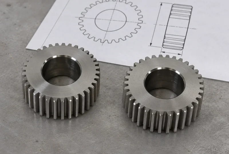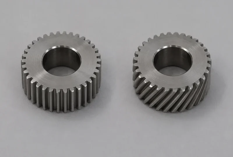



Gear hobbing is a strong candidate when an external gear’s tooth geometry, blank design and tool access suit the generating process. It should be selected with the whole manufacturing route in view: soft cutting, any heat treatment, finishing allowance and final inspection. A gear’s tooth count and module alone are not enough to confirm that it can be hobbed as drawn.
For automotive component buyers, the useful question is whether hobbing fits the actual gear or integrated shaft, at the required delivery condition and quantity. The process name does not establish a finished accuracy grade or a particular supplier’s capability.
How the generating process differs from form milling
In hobbing, a toothed hob and the workpiece rotate in a coordinated relationship while the cutting motion generates the gear teeth. The final tooth form comes from that relative motion, rather than simply copying a single cutter profile into one stationary tooth space. TEA Hamburg’s manufacturing glossary describes this continuous generating relationship.
This distinction matters when evaluating a drawing change. A change to tooth geometry can affect the required hob, machine setup and inspection, even if the finished outside diameter appears similar. Ask the manufacturer to review the full tooth definition, including modifications and the normal or transverse system where relevant.
Check access before debating cutting speed
The hob needs a workable approach, cutting path and exit. An adjacent shoulder, large flange, second gear or shaft feature can restrict that path. A CAD model showing a complete tooth surface does not prove that the cutting tool can reach it.
For an integrated gear shaft, provide the surrounding geometry and proposed workholding references. The manufacturer should review the cutter envelope, clearance and fixture access together. Moving a shoulder or adding a relief may help a route, but such a change needs design approval because the feature can also serve a locating or strength function.
| Drawing feature | Question for route review | Information to supply |
|---|---|---|
| External teeth | Does the tooth definition suit the proposed generating tool? | Complete gear data and any profile or lead modifications |
| Shoulder near the teeth | Is there adequate cutter approach and exit space? | Axial distance, shoulder diameter and allowed relief geometry |
| Integrated shaft | Can the part be located and supported without obstructing cutting? | Full shaft model and functional datum requirements |
| Thin or flexible blank | How will clamping and cutting affect the workpiece? | Wall sections, material condition and permitted holding surfaces |
| Later finishing | Which surfaces need controlled stock after cutting? | Treatment route and finishing requirements |

Plan hobbing within the finished-part route
Many manufacturing routes cut teeth before hardening and use later operations to meet the final requirements. The agreed route must identify what is accepted at the hobbing stage and what is accepted only after treatment and finishing.
Do not demand the final finished tooth thickness at the soft-cut stage if the approved route intentionally leaves material for finishing. Conversely, a satisfactory soft-cut report is not evidence that the treated, finished part meets the final drawing. Identify the intermediate requirement and the final requirement separately.
A practical route review should state the input material condition, locating features used during cutting, tooth and flank stock where required, treatment responsibility, finishing operation and final inspection references. Any assumed stock or distortion allowance needs agreement with the responsible manufacturing and design teams.
When shaping deserves a comparison
Conventional external hobbing is not the default answer for an internal gear. Shoulder-limited geometry may also justify examining another process. Gleason describes gear-shaping equipment for internal and external spur and helical gears.
That makes shaping a candidate, not an automatic solution. Its cutter stroke and clearance must still suit the part. Compare the actual blank, tool availability, quantity, required accuracy and downstream operations. Where another process is proposed, ask for the same finished-part acceptance basis so quotations remain comparable.
Use inspection trends to guide process control
For production planning, ask which intermediate characteristics will be monitored and how the tool’s condition is controlled. The selected checks might include tooth thickness, specified profile or lead characteristics, pitch-related results, burr condition and references needed by later operations.
A change in a measured characteristic can prompt a tool-condition or setup review, but it does not uniquely diagnose tool wear. Workholding, blank variation, measurement setup and machine conditions can also contribute. Retain part sequence and tool-change information so investigation uses evidence rather than a visual guess.
Specify the final gear-inspection standard and characteristics required by the drawing. “CNC hobbed” describes a manufacturing operation; it is not an acceptance report.
What to send for a hobbing feasibility review
Send the complete drawing and model, mating gear information where relevant, material and treatment requirements, annual forecast and order-release quantities. Highlight shoulders close to the tooth face, restricted holding surfaces and any geometry that cannot change.
For TAITECH’s custom gears and gear shafts, use the drawing-review enquiry to confirm a feasible route and inspection scope. Request the supplier’s exceptions and assumptions alongside the quotation, especially where cutting access or post-treatment finishing remains unresolved.