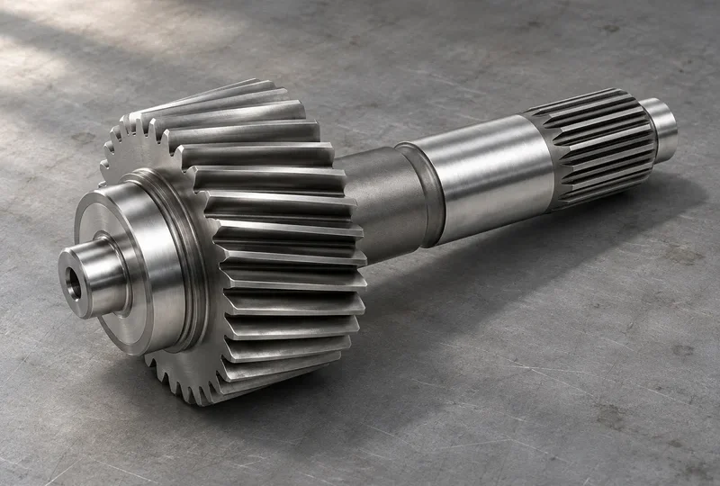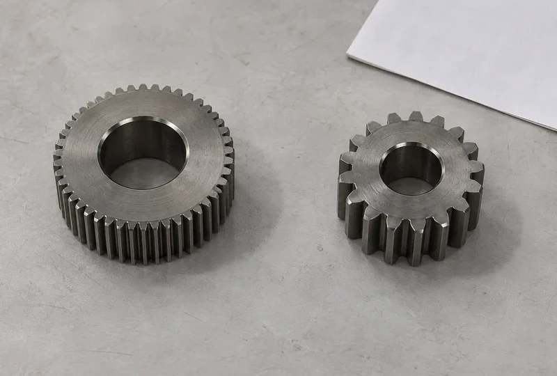


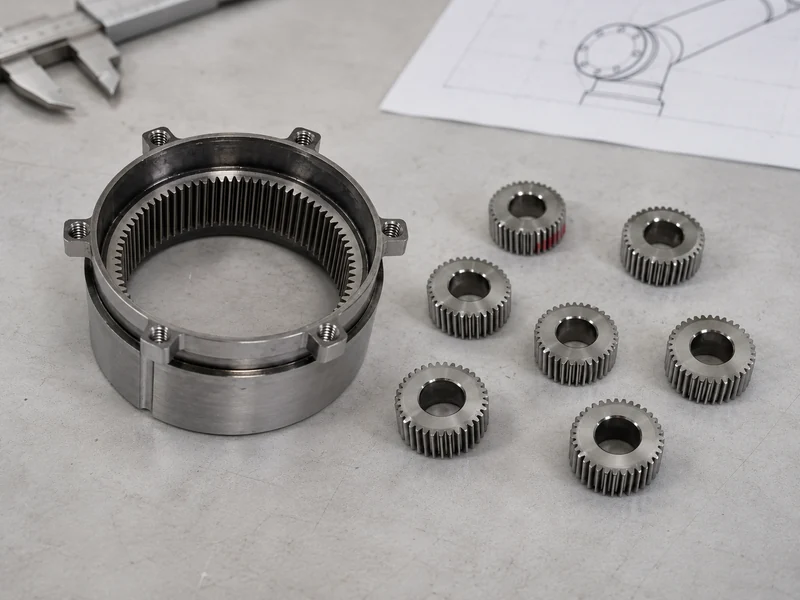
Choose a robot joint reduction architecture by comparing candidate assemblies against the joint’s motion, torque spectrum, stiffness, lost motion, thermal behavior and installed envelope. Planetary, strain-wave and cycloidal mechanisms have different constructions, but the architecture name alone does not determine which joint will position more accurately or tolerate the intended duty.
Start with the required motion and load cases, then shortlist actual reducer configurations. Comparing a bare planetary component set with a fully supported cycloidal reducer produces an incomplete decision, even when both catalogues show the same nominal ratio.
Describe the joint before selecting its reducer
Record the required angular travel, velocity, acceleration, reversals, payload-related torque, external moments and operating cycle. Distinguish continuous operation, short peaks and exceptional events. The responsible system engineer must define how each case will be assessed.
For joints involving controlled contact, also define the required response to external torque and the sensing arrangement. Low-load friction, compliance and backdriving behavior can matter alongside rated output torque. A single efficiency value at a rated point does not describe all of those behaviors.
Document the available diameter and axial length, cable or service-routing needs, mounting interfaces, cooling assumptions and output-bearing requirements. These constraints often remove unsuitable candidates before a detailed architecture comparison is necessary.
Understand the mechanisms without assigning universal ratings
| Architecture | Basic mechanism | What to investigate in the candidate |
|---|---|---|
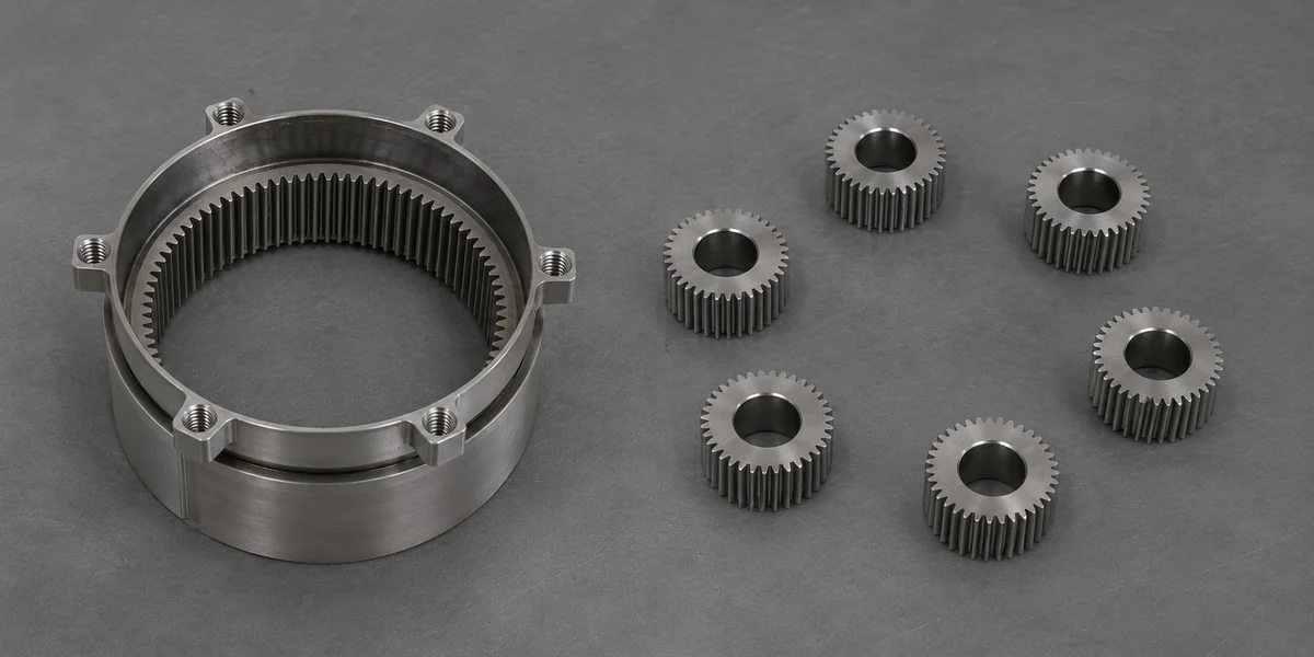
| Planetary | Sun and planet gears mesh with an internal ring; a carrier positions the planets | Stage count, mesh clearance, supports, load sharing and complete assembly stiffness |
| Strain-wave | A wave generator elastically deforms a flexspline into engagement with a circular spline | Torque-dependent behavior, input and output support, mounting and specified life conditions |
| Cycloidal | Eccentric motion drives cycloidal elements against their surrounding engagement elements | Integrated stages, support bearings, moment loads, installation and lubrication requirements |
Harmonic Drive describes its strain-wave mechanism through the wave generator, flexspline and circular spline. Its brand and product claims should not be treated as measured performance for every strain-wave design or complete robot joint.
Similarly, Nabtesco’s RV catalogue illustrates a spur stage together with an eccentric cycloidal stage. This is a specific architecture implementation, not a universal construction drawing for all cycloidal reducers.
For the planetary component roles, see the sun, planet, ring and carrier overview.
Compare the same measurement, under the same conditions
Backlash, lost motion, torsional stiffness, transmission error and repeatability describe different aspects of behavior. A reducer advertised with no geometric tooth backlash can still have elastic deflection under torque. An unloaded positional result cannot be assumed to represent the loaded joint.
Ask each supplier for definitions and test conditions. Record which shaft is restrained, the applied torque sequence, temperature, speed where relevant, measurement location and whether the result includes the output bearing and housing. Keep values in their original units until the basis for conversion is clear.
| Comparison item | Common basis to establish |
|---|---|
| Output torque | Continuous, repeated peak and exceptional-event definitions; duty and life assumptions |
| Lost motion or backlash | Torque range, restraint, direction reversal and measurement location |
| Stiffness | Torque region and whether the figure represents the reducer alone or installed joint |
| Efficiency and friction | Speed, load, lubricant and temperature, including low-load behavior where needed |
| Mass and envelope | Included bearings, housing, couplings, seals, brake and routing provisions |
| Life evidence | Load spectrum, speed, lubrication, temperature and maintenance basis |
If one supplier cannot provide a comparable value, retain an open evidence item. Converting an unknown into an assumed score makes the comparison appear more complete than it is.
Count the parts needed to install the joint
A bare reducer component set may require the buyer to design the housing, bearing supports and output interface. A packaged reducer may include some of those elements. Compare the final joint layout and bill of materials rather than catalogue reducer mass alone.
Consider assembly access, fastening, bearing preload or clearance responsibilities and inspection after installation. For a hollow routing requirement, confirm the usable passage and the surrounding interfaces in the proposed configuration; a central opening in a photograph is insufficient.
Also identify responsibility for the motor coupling, encoder location and brake integration. These components can affect packaging and observed joint performance even though they are outside the reducer’s basic gear mechanism.
Build a shortlist with explicit validation questions
Use the following sequence instead of a universal “best reducer” ranking:
- Eliminate incompatible envelopes and interfaces. Confirm the candidate can fit with the required supports and routing.
- Check duty definitions. Match torque, speed and cycle assumptions to the joint requirement.
- Compare motion behavior. Resolve the definitions behind accuracy, lost motion, friction and stiffness values.
- Review integration responsibilities. Identify what the reducer supplier provides and what the joint team must design and verify.
- Validate the remaining candidates. Agree the assembly configuration and tests that answer the remaining application questions.
For a hypothetical frequently reversing joint, the shortlist might remain open until loaded reversal behavior and temperature are compared. For another joint, an installed-envelope constraint may settle the shortlist first. The decision follows the application and evidence rather than the popularity of the mechanism.
Where a custom planetary-component enquiry fits
Once the system team selects a planetary route, it can define the sun, planets, ring and shaft interfaces for manufacture. A custom component enquiry should identify the approved architecture, drawings, material and treatment requirements, quantities and required inspection evidence.
TAITECH’s gear and gear-shaft components are the relevant supply discussion. The planetary component images shown here do not represent complete strain-wave or cycloidal reducers. Send your component drawings and supply scope for review, separating the manufacturing request from any unresolved complete-joint design or validation responsibilities.