

A hollow shaft of the same outside diameter as a solid shaft weighs less and has lower torsional and bending stiffness. If you allow a larger outside diameter while holding mass constant, a hollow section can be stiffer. Set the comparison first. A motor with fixed bearing and seal interfaces may give you very little room to increase the diameter.
Compare the section on equal terms
For a uniform circular shaft with outside diameter D and bore diameter d, area is π(D² − d²)/4. The polar second moment J is π(D⁴ − d⁴)/32. The second moment for bending about a centroidal diameter is J/2. With the same material and length, mass follows area and elastic torsional stiffness follows J. These are section calculations for concentric, circular geometry.
| Hypothetical geometry | Mass relative to the solid shaft | J relative to the solid shaft |
|---|---|---|
| 40 mm solid | 1.00 | 1.00 |
| 40 mm outside, 24 mm bore | 0.64 | 0.8704 |
| 50 mm outside, 30 mm bore | 1.00 | 2.125 |
The 50 mm section puts more material farther from the axis and needs another 5 mm of radial space. For the same applied torque T, compare the outer-fiber shear stress using T × (D/2) / J. Allowable torque also depends on the material condition and the local features that the uniform section model leaves out.
Check the smallest wall in the actual shaft
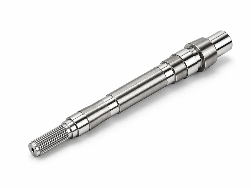
A stepped motor shaft rarely has a uniform wall. Mark the section through each journal, spline root and shoulder. A bearing fit can load the remaining wall and affect the assembled shape. The spline root may leave less wall than the nominal diameter suggests. Include these local sections and fillets in the stress review.
Look at the whole rotor before drawing conclusions about critical speed. The bearing stiffness, mass and position of the mounted rotor components, and shaft geometry all enter that assessment. The section table helps screen shapes. The assembled model determines how the change affects critical speeds. COMSOL rotor analysis examples.
Give manufacturing a bore it can verify
Specify which bore features serve a function, where wall thickness is checked, and which surfaces set the reference axis. If a proposed construction joins pieces, include the joint location and the inspection after joining. A cooling passage also needs its own requirements and verification. EMAG’s example of an assembled rotor shaft.
Start with a solid concept when the envelope is tight and there is no functional use for the bore. For a weight reduction study, send the shaft sections, permitted envelope, fit requirements and loads for both concepts. Request a shaft feasibility review.