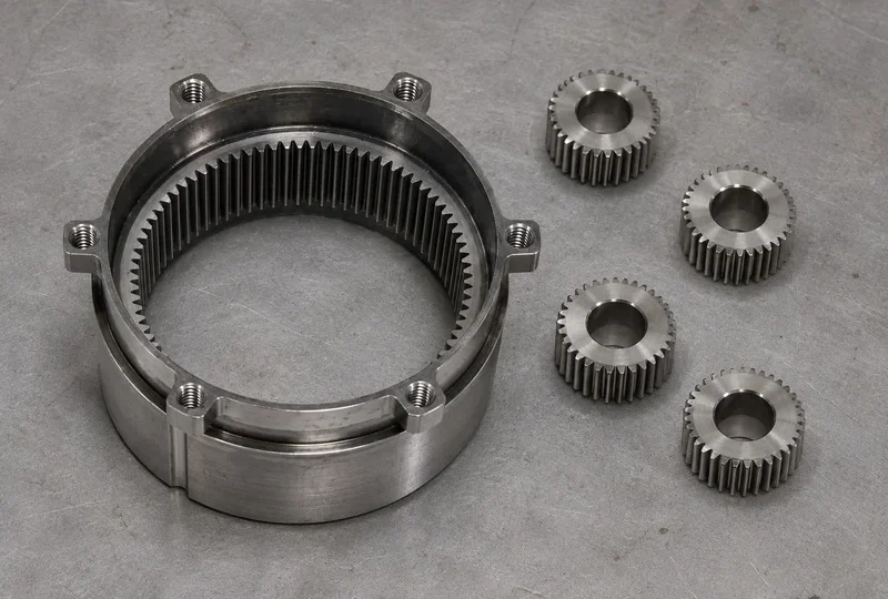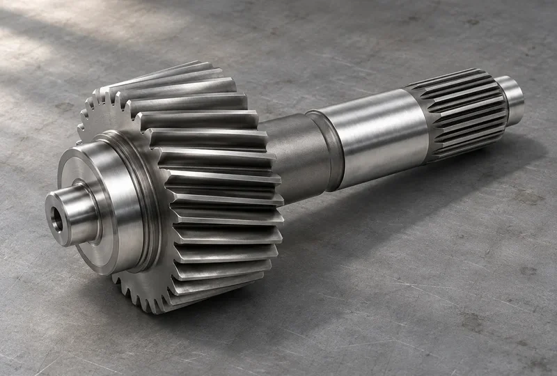


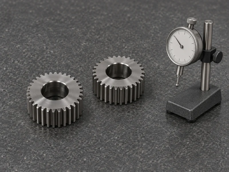
To measure gear backlash with a dial indicator, hold one gear stationary and rock the other between its two flank contact positions. Record the travel at a stated radius and under a defined reversal load. If someone gives you a second reading from an encoder on the output shaft, check which parts moved before you try to reconcile the numbers.
Decide what the result will describe
For backlash of a single mesh, mount the mating gears at the specified center distance and support the shafts so they stay in their intended positions. Hold one member without letting its support move. If the requirement is for lost motion through an assembled reducer, use the specified input and output interfaces. That test can include play from several meshes, couplings and bearings. Put the measurement boundary on the report.
Circular backlash is an arc length on a stated pitch circle. Angular backlash is rotation about a stated gear or shaft axis. Normal backlash is measured in a different direction across the tooth clearance. Report the quantity named on the drawing, or ask the drawing owner how the reading should be converted before accepting the part. See SDP/SI’s backlash reference.
Set up the indicator and repeat the reversal
- Identify the mating gear, the locked member and the member that moves. Check the mounting distance and bearing seating. In a helical pair, axial movement can change the reading, so use the specified axial restraint.
- Set the indicator against a suitable measuring arm or surface, with its sensing direction tangent to the motion. Record the distance from the free shaft axis to the point of contact. Confirm that the stand and shaft lock stay seated when you reverse the load.
- Apply the agreed torque in one direction to seat the flanks, then apply the specified torque in the opposite direction. Read the travel between those positions. Use the same loading sequence at each position, including any dwell or settling requirement.
- Index the mesh to the positions in the inspection plan. Keep the individual readings and the minimum and maximum. An average can hide a tight spot when runout or tooth variation changes the clearance around the gear.
If the indicated travel rises when the test torque increases, check the fixture, bearings and shaft for deflection. The difference can include elastic movement after tooth contact. Agree on the load or torque used for acceptance before comparing results from two setups. A double flank rolling test runs the gears in contact and observes center-distance variation. It answers a different inspection question from this free-motion measurement. See Gleason’s description of flank testing.
A reading of 0.08 mm at a 40 mm radius
For small rotation with tangential indicator alignment, angle in radians is approximately travel divided by radius. In this example, 0.08 / 40 = 0.002 rad, or about 0.115°. If the agreed working pitch radius of the same free gear is 25 mm, the corresponding arc length there is 25 × 0.002 = 0.05 mm. Both lengths describe the same rotation. The 40 mm radius belongs to the measuring setup, while the 25 mm radius belongs to the reporting convention.
For a larger movement or an angled probe, use the measurement system’s geometry or an angular instrument. A tangent approximation assumes small movement, a known contact radius and no appreciable slip in the fixture.
Fields that make two reports comparable
| Record | What to write down |
|---|---|
| Parts and mounting | Pair or master identification, assembly revision, center distance, support and axial condition |
| Reversal | Locked member, free member, torque in each direction, temperature and lubrication condition |
| Reading and result | Instrument, probe direction, measuring radius, reporting radius or shaft, units and sampled positions |
For a custom gear review, attach the drawing, mating gear data and acceptance method. If you are still deciding where to allocate clearance, see the guide to tooth thickness and center distance.