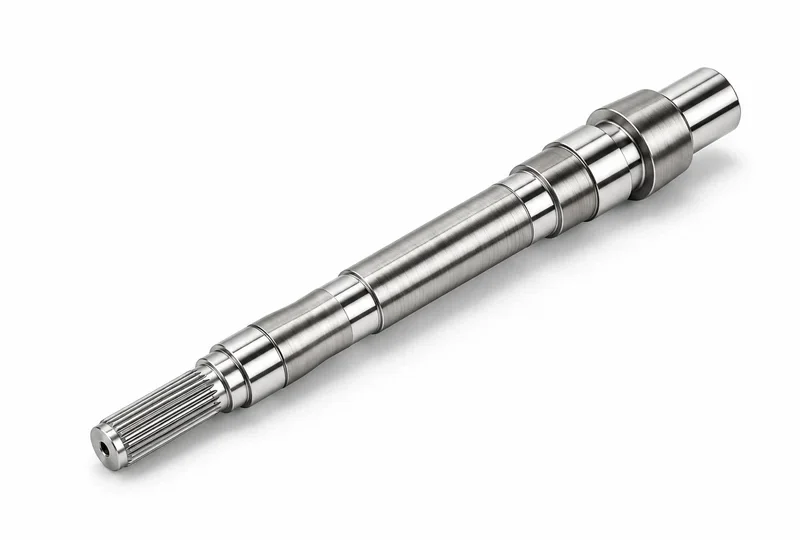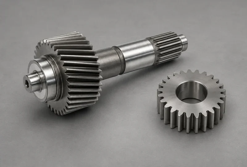


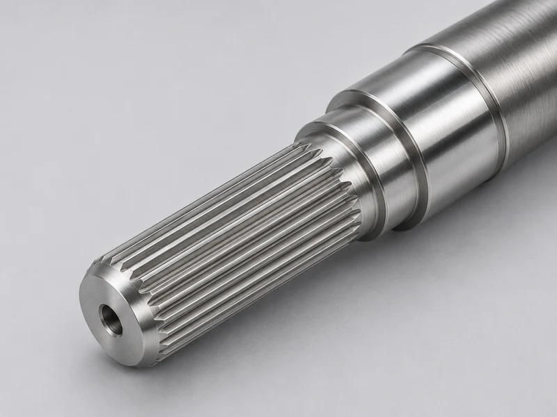
A spline shaft drawing needs enough information to manufacture the external teeth, check them and assemble them with the correct hub. A CAD tooth shape gives the supplier nominal geometry. Add the governing standard and edition, the fit designation and the inspection requirements before you release the drawing.
Give the shaft and hub a common reference
Name the spline system, tooth count, size convention and pressure angle. State that the callout is for the external member and identify the mating hub drawing and revision. Add the fit or tolerance designation in the syntax of the selected standard. For example, ISO 4156 applies to metric module, straight cylindrical involute splines with side fit. Use its applicable parts for the design and inspection details. ISO 4156-1 scope.
Mark the limits at each end of the teeth
Major and minor diameters describe the large and small diametric boundaries. Which lies at the tooth tips depends on whether the drawing shows the external shaft or internal hub. Form diameter identifies a limit of the specified working tooth form under the applicable convention. Give the relevant values and tolerances from the standard or the released design.
Dimension the usable engagement separately from the overall spline length. A chamfer or cutter runout can occupy part of that overall length. If the hub must seat against a shoulder, give the axial distance between the seating face and the end of usable tooth form. Show any relief required for the tool to exit. For a sliding connection, also define the travel over which the fit must work.
Make the part testable after finishing
| What must work | Information to put on the drawing or inspection plan |
|---|---|
| Hub fits on the shaft | Mating reference, fit designation and applicable functional gage requirement |
| Individual tooth dimensions meet limits | Specified elemental checks, such as an over-pin measurement with the applicable pin and setup details |
| Assembly runs on its intended axis | Functional datum and geometric controls relating the spline to the journals or other locating surfaces |
| Fit remains valid at delivery | Condition at inspection after heat treatment, coating or finishing as applicable |
A functional gage and a dimensional reading cover different aspects of acceptance. Agree on the actual gage, the characteristic it checks and how its result is recorded. If the buyer supplies a sample hub, identify its revision and intended role in the fit check. ISO 4156-3 inspection scope.
Before asking for a quote, put the shaft and hub drawings side by side. Check that the fit, engagement length and inspection stage refer to the same assembly condition. Send both drawings and call out any missing mating data. Submit a custom spline shaft inquiry.